+86-731-89578196
 [email protected]

- Home
- Our Company
-
Products
Sputtering Targets
- Industries
- Blog
- FAQ
- Contact Us
Types of Substrates and Wafers
Single Element Semiconductors
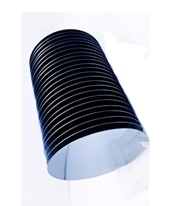
Silicon, Si - the most common semiconductor, atomic number 14, energy gap Eg = 1.12 eV - indirect bandgap. crystal structure - diamond, lattice constant 0.543 nm, atomic concentration 5x10²² atoms/cm-3, index of refraction 3.42, density 2.33 g/cm3, dielectric constant 11.7, intrinsic carrier concentration 1.02 x 1010 cm-3, mobility of electrons and holes at 300 K: 1450 and 500 cm2/V-s, thermal conductivity 1.31 W/cm-oC, thermal expansion coefficient 2.6 x 10⁻⁶ 1/oC, melting point 1414 oC. excellent mechanical properties (MEMS applications). Single-crystal Si can be processed into wafers up to 300 mm in diameter.
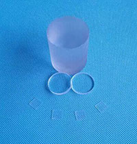
Silicon on Insulator (SOI)
Only a thin layer on the surface of a silicon wafer is used for making electronic components. The rest serves nearly as mechanical support. The role of SOI is to electronically insulate a fine layer of monocrystalline silicon from the rest of the silicon wafer. Integrated circuits can then be fabricated on the SOI wafers' top layer using the same processes as would be used on plain silicon wafers. The embedded layer of insulation enables the SOI-based chips to function at significantly higher speeds while reducing electrical losses. The result is an increase in performance and a reduction in power consumption. There are two types of SOI wafers. Thin-film SOI wafers have a device layer <1.5 μm, and thick film wafers have a device layer >1.5 μm.
Substrates for III-V Semiconductors
Gallium Arsenide, After silicon second the most common semiconductor. Due to GaAs evaporation, does not form sufficient quality native oxide, mechanically fragile, due to direct bandgap commonly used to fabricate light-emitting devices, due to higher electron and hole mobilities, also the foundation of the variety of high-speed electronic devices, the bandgap can be readily engineered by forming ternary compounds based on GaAs, e.g., AlGaAs.